The Battery Bay can be used for mounting power system accessories including high capacity batteries, tethers, fuel cells and alternative energy sources.
The Battery Bay mechanical interface points with Solo are:
We recommend you enclose your power solution using the battery bay envelope, as this correctly implements the required mechanical interface points. The battery bay envelope CAD file can be downloaded from here.
The electrical interface with Solo uses the following connectors:
Battery side connector (female) is a Molex 171090-0048 (PDF). This is a custom connector that can only be purchased in minimum orders of 1,000 units.
Solo / charger side connector (male) is a Molex 171088-0048 (PDF)
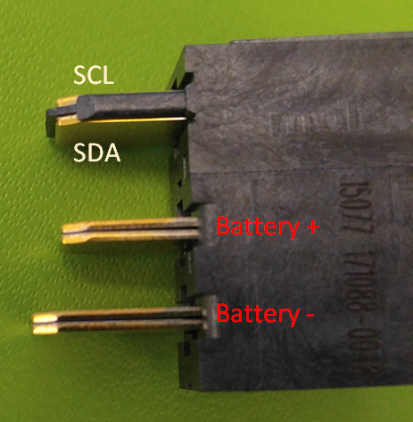
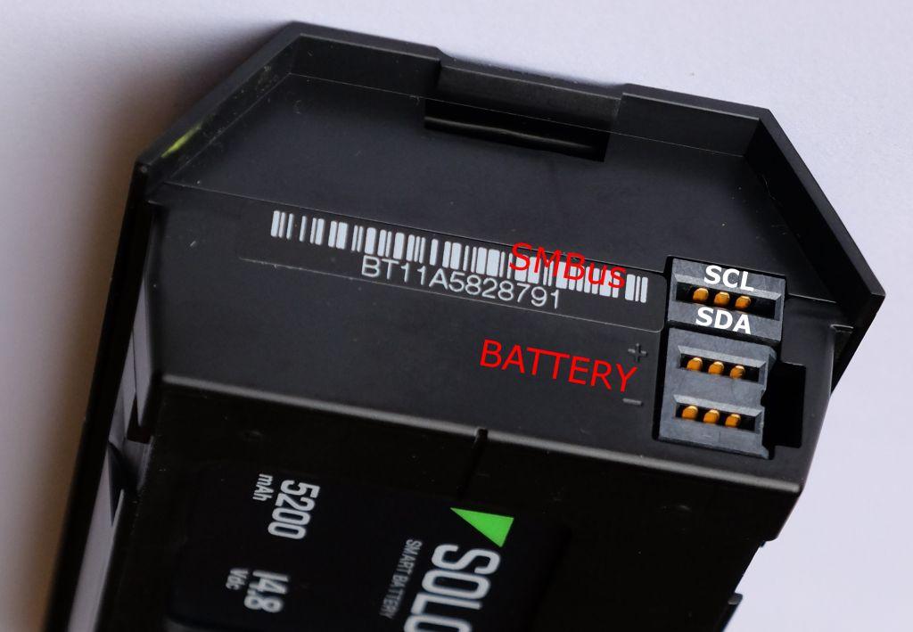
The battery interface has 3 prongs with 4 contacts. The SMBus connector has 2 contacts: SCL (top) and SDA (bottom) on the top-most prong. The Battery + and - are the bottom 2 prongs. The battery and SMBus must share a common ground.
The connector contacts are rated for 40A on the power contacts.
Battery bay payloads should have approximately the same physical and electrical characteristics as the current battery: Solo Battery Specifications.
The recommended physical characteristics are:
Changing the battery weight will have a corresponding impact on the weight available for accessories. The center of gravity must remain close to the current location.
The main physical characteristics are:
It is up to the power system manufacturer to make sure all safety and regulatory certifications (including UL) are obtained. The power system must not have a low-voltage or low-capacity cut-off.
Solo uses the standard SMBUS spec for communicating with the battery. To interface with the battery it is best to implement the full specification.