The Gimbal Bay provides an extensible interface intended for attaching Made For Solo-approved 3-axis gimbal and camera solutions.
The Gimbal Bay area comprises the lower-front area of Solo, extending back as far as the accessory bay and into the vehicle body.
The mechanical interface points with Solo are:
The 3DR Gimbal Bay Body Pan (as used for the 3DR Gimbal) is shown below. Third-party gimbals will need to use a plate with the same relative fastener positions.
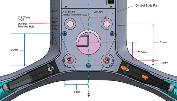
The gimbal will require isolation from copter structural/vibrational modes. Gimbals that use a similar damper system to the 3DR Gimbal may also need the same damper hole spacing.
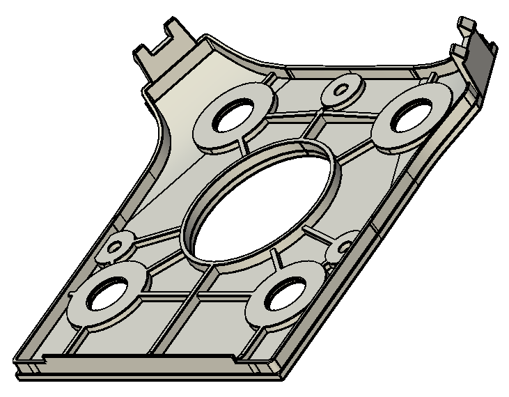
We recommend that you use the Solo Gimbal Beauty Plate as the starting point for your own plate, as it correctly implements the required mechanical interface points. The CAD file for the plate can be downloaded from here and a screenshot is shown below.
The space within the Gimbal Bay cavity is extremely limited. It is important to allow sufficient clearance for gimbal movement as shown in the diagram below.
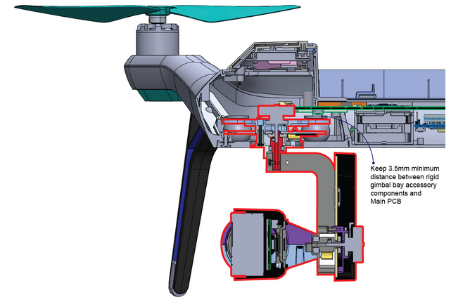
Ensure that the camera is in an appropriate position to avoid propellers in the frame during pitch maneuvers (maximum copter pitch angle = 38°).
The recommended payload requirements are:
The gimbal should operate effectively within the following environmental conditions:
* The maximum payload of Solo with gimbal, camera and other accessories is 700g. Camera/Gimbal solutions that exceed the weight of the 3DR Gimbal and GoPro (390g) may not work with all accessories.
There are two physical connections from the Solo to a gimbal. The Solo Gimbal Cable, which primarily manages the position and recording state of the camera, and the HDMI Micro cable which routes the video signal.
The Solo Gimbal cable terminates in a Molex 5031490800 (alt link) connector. A gimbal board is connected using the corresponding Molex 5031540890 (alt link) connector.
| Pin | Name | Color | Description |
|---|---|---|---|
| 1 | VCC Battery | Red | 12V to 16.8V. Max recommended current/power is ~3A/50W. Drawing additional current may damage the battery and increases the risk of accident. |
| 2 | VCC 5V | Yellow | 4.75V to 5.4V voltage pin for Camera (only). Current should be less than 1A. |
| 3 | GND (Gimbal) | Black | |
| 4 | GND (USB) | Brown | |
| 5 | Gimbal Rx | White | |
| 6 | Gimbal Tx | Green | |
| 7 | USB D+ | Blue | Positive differential data signal to iMX6 OTG USB port. |
| 8 | USB D- | Violet | Negative differential data signal to iMX6 OTG USB port. |
The Gimbal Cable supplies two different voltage sources to the Gimbal Bay:
VCC 5V should be used to power the camera (only). The camera must not draw more than 1A.
VCC Battery can be used to power the gimbal or other hardware. The maximum recommended current/power is ~3A/50W. Drawing more current may damage the battery and increases the risk of accident.
The Gimbal TX and Gimbal RX lines send MAVLink data over a serial connection between the Pixhawk flight controller and the gimbal. This connection is used to both control the pitch, roll, and yaw of the gimbal motors as well as send commands over to the camera (start recording, stop recording, change modes, etc). More details on camera control can be found in the Software Interface section.
The Gimbal Cable provides a USB 2.0 interface with the iMX6 co-processor on-board Solo. This interface should be used for firmware updating and can optionally be used for any sort of additional processing. For example, you can pull a still from the camera, transfer it to the co-processor, and search the image for pre-defined target.
The HDMI Micro (Type D 19P) cable transfers video from the camera to Solo's i.MX6 Companion Computer (from which it is sent to the first person view in the Solo app). The HDMI connection does not have the audio pins connected. The video feed supports up to 1080p resolution at 60 frames per second.
Supported resolutions:
Communication between Solo and gimbal is done using MAVlink Protocol over Serial. Messages are used for
In order to have Solo control a gimbal, ArduPilot must know how to communicate with the gimbal. Fortunately, ArduPilot already has the ability to communicate with several types of pre-existing gimbal controllers including SToRM32 and Alexmos. The custom Solo Gimbal protocol is not yet supported by any released versions of ArduPilot.
SToRM32 is recommended as it features the most straightforward communication protocol. You can find more information about this type of gimbal controller here and ArduPilot integration can be found here.
There are a set of camera functions that are common amongst all gimbal/camera systems. These functions include START RECORDING/STOP RECORDING, POWER ON/OFF, & CHANGE MODES.
However, 3rd party developers cannot currently take advantage of the pre-set camera-related buttons on the Solo controller because they are sent as GoPro specific commands.In addition, there is not yet a way for 3rd party developers to capture any button events on the Solo co-processor or ArduPilot.
COMMAND_LONG is the recommended MAVLink command for any unique, custom camera or gimbal functionality:
| Byte index | Value Size (bytes) | Value Description | Value |
|---|---|---|---|
| 0 | 4 | Param 1 | {DEPENDENT ON COMMAND} |
| 4 | 4 | Param 2 | {DEPENDENT ON COMMAND} |
| 8 | 4 | Param 3 | {DEPENDENT ON COMMAND} |
| 12 | 4 | Param 4 | {DEPENDENT ON COMMAND} |
| 16 | 4 | Param 5 | {DEPENDENT ON COMMAND} |
| 20 | 4 | Param 6 | {DEPENDENT ON COMMAND} |
| 24 | 4 | Param 7 | {DEPENDENT ON COMMAND} |
| 28 | 2 | MAV_COMMAND (User defined command) | {DEPENDENT ON USE CASE} |
| 30 | 1 | Target System | 0 |
| 31 | 1 | Target Component | MAV_COMP_ID_GIMBAL |
| 32 | 1 | Confirmation Number | Nth time packet was sent |
COMMAND_LONG essentially gives MAVLink consumers the ability to define their own commands without worrying about whether it already exists in the MAVLink spec or if other developers are writing a conflicting spec. It is essentially a packet within a packet. 3rd party developers can define their own commands (MAV_COMMAND, byte 28 above) and up to 7 parameters to send along with that command. Their application can capture the COMMAND_LONG packet header and then parse the custom MAV_COMMAND identifier to route the packet to the appropriate handler.